Have you ever wondered how to get more accurate miter saw cuts while working on-site?
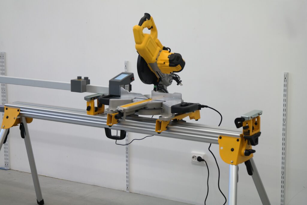
In this guide, we will show you how to mount the Pedante digital miter saw fence on a portable miter saw stand and turn it into a more accurate, repeatable cutting station for out-of-workshop use.
The stand used in this example is a DeWALT DE7023-XJ, also known as the DWX723 in some markets, with additional work supports. This is only the setup used for this guide – the same basic mounting principles can be adapted to other miter saw stands, as long as the stand is rigid enough and the support points can be adjusted correctly.
This tutorial covers the mounting position, support setup, alignment, first setup, and other practical details that matter when using a Pedante automated length stop. You can view a video version of the tutorial here.
Before starting, please note that every miter saw and stand combination is slightly different. Check your own saw, supports, brackets, and available mounting points before drilling or tightening anything permanently.
What will you need?
Main:
• 1x Pedante LS-24-U Digital Miter Saw Fence
• 1x portable miter saw stand (In this example: DeWALT DE7023-XJ / DWX723)
• 1x extra miter saw stand support (In this example: DeWALT DE7024)
• 1x miter saw
Attachments:
• 2x T-head Bolts (Included with Pedante LS-24-U)
• 2x DIN6334 M8 extended nuts
Tools:
• Wrench
• Screwdriver
• Square
• Marker
• Center punch
• Hammer
• Drill
• Drill bits – 5 mm for pilot hole, 8 mm for main hole
• Straight piece of wood / metal
• Tape measure (For calibrating Pedante)
The exact wrench and screwdriver depend on the stand and work supports you are using. Check the nuts and screws on your own support before starting.
Basic Mounting Idea
Before going into the steps, it is important to understand what the mounting needs to achieve.
The Pedante rail must follow the same path as the material being cut. It should be straight, level, and parallel to the saw fence. The stop block must contact the end of the workpiece squarely.
The workpiece should sit flat on the saw table and on the support area. It should not lift up, tilt, or sag when pushed against the stop.
The mounting also needs to be solid. When material is pushed gently against the Pedante stop block, the rail and support brackets should not move.
These rules are the same for any miter saw stand. The brackets and mounting holes may be different, but the important points are always the same:
- The rail must be straight.
- The rail must be level.
- The rail must be parallel to the material path.
- The stop block must be square to the material.
- The support must not move during use.
Step 1: Install the Miter Saw on the Stand
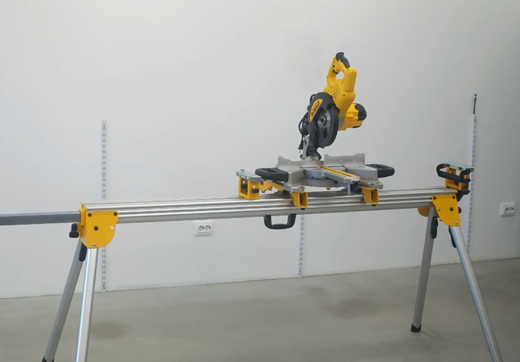
Mount the miter saw on the stand first.
The saw position determines where the Pedante rail needs to sit, so the saw should be fixed in place before aligning the length stop system. In this setup, Pedante is mounted on the left side of the saw. You can also mount it on the right side, depending on your workflow and available space.
Before tightening the saw brackets, check if:
- The saw is sitting securely on the stand.
- The saw table is not twisted.
- The saw fence is easy to access.
- There is enough space for the Pedante control unit near the saw.
- Long pieces of material can pass through the cutting station without hitting anything.
- The moving stop block will have enough travel.
Once the saw is positioned correctly, tighten the saw mounting brackets according to the stand manufacturer’s instructions.
Then install the two work supports that came with the stand. Place one support on each side of the saw.
Step 2: Prepare the Extra Work Support
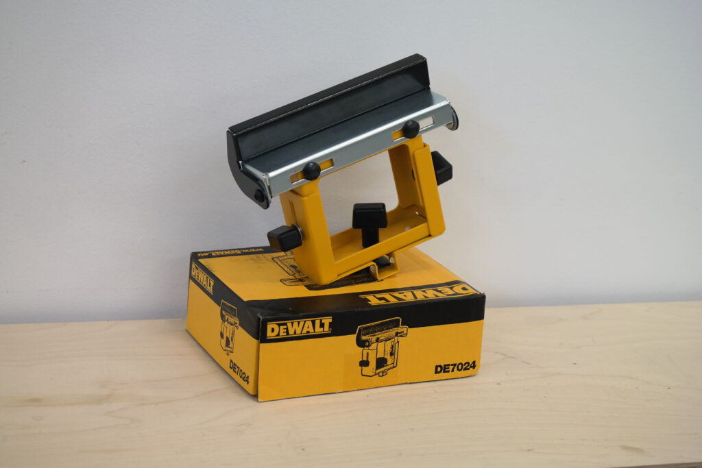
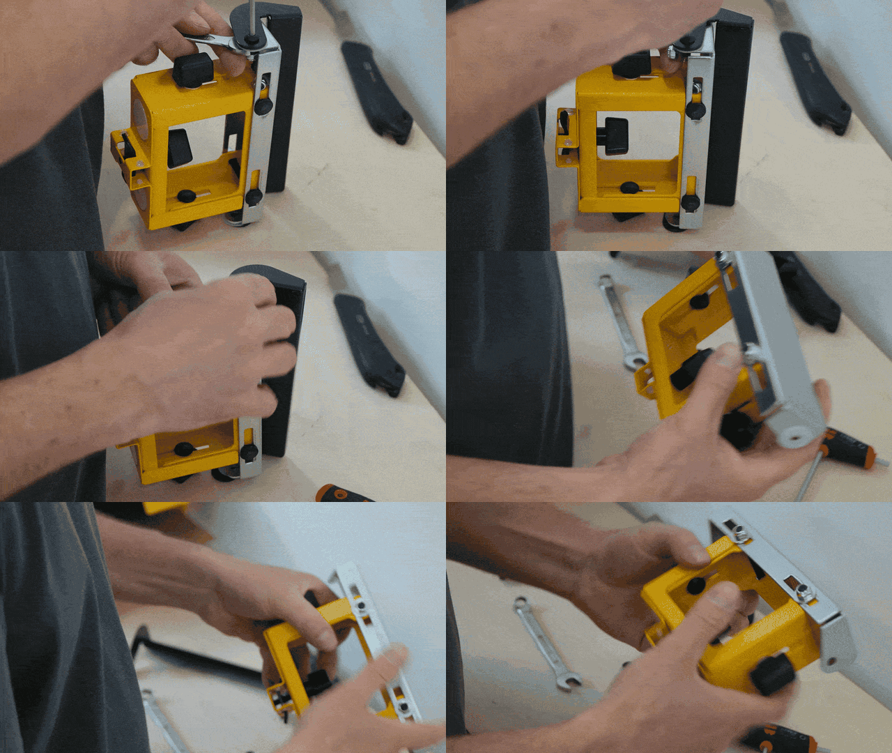
For this setup, we use a third work support on the same side where Pedante will be mounted.
Take the extra work support and remove the original length stop from it. On this support, the length stop is the black part at the end. Use a wrench to loosen the nuts and a screwdriver to hold the bolts in place, if needed. Set the removed length stop and its hardware aside. Keep these parts in case you want to return the support to its original configuration later.
Step 3: Move the Height Adjustment Knob
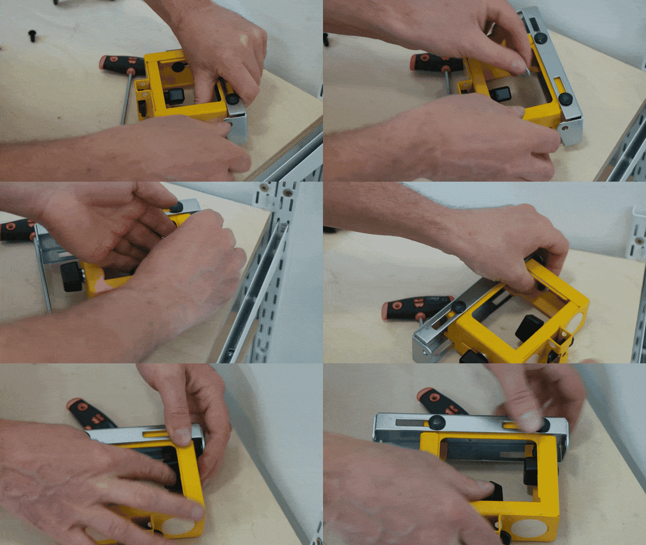
Unscrew one of the height adjustment knobs on the support. Move it from the outside of the support to the inside, then screw it back in. This creates space for the T-head bolt and extended nut used to mount the Pedante rail. Without moving the knob, the mounting hardware may not have enough clearance.
After moving the knob, check that the height adjustment still works correctly. The support should still move up and down and lock firmly.
Step 4: Attach the Extra Support to the Stand
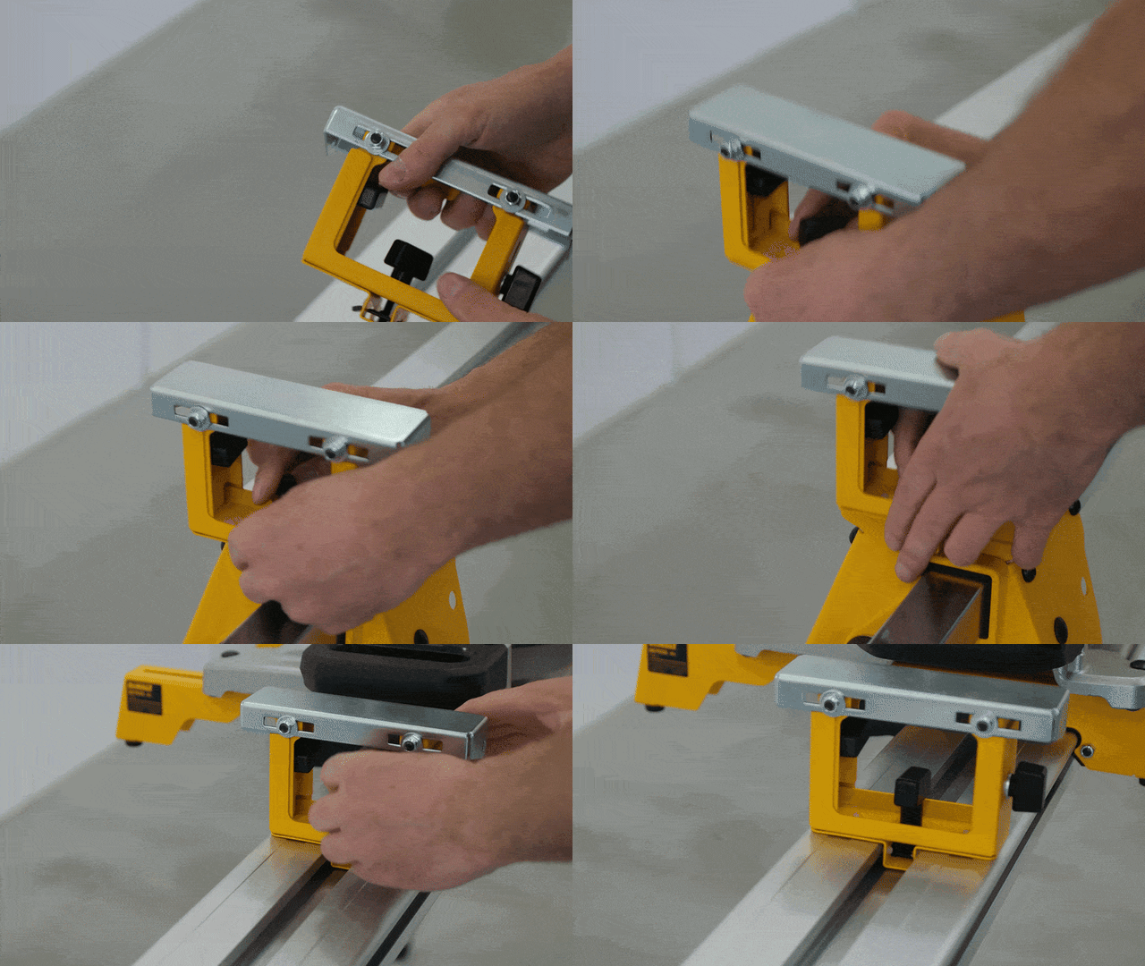
Attach the extra support to the stand on the same side where Pedante will be mounted. Loosen the support’s tensioning knob until the support can slide into the stand groove. Slide it into position, then tighten the tensioning knob enough so the support stays in place.
Do not place the support randomly. Think about where the Pedante rail will sit and where the two T-head bolts need to be located. You can still adjust the support position later, but it is easier if the rough position is close from the start.
Step 5: Move the Workpiece Support to the Side
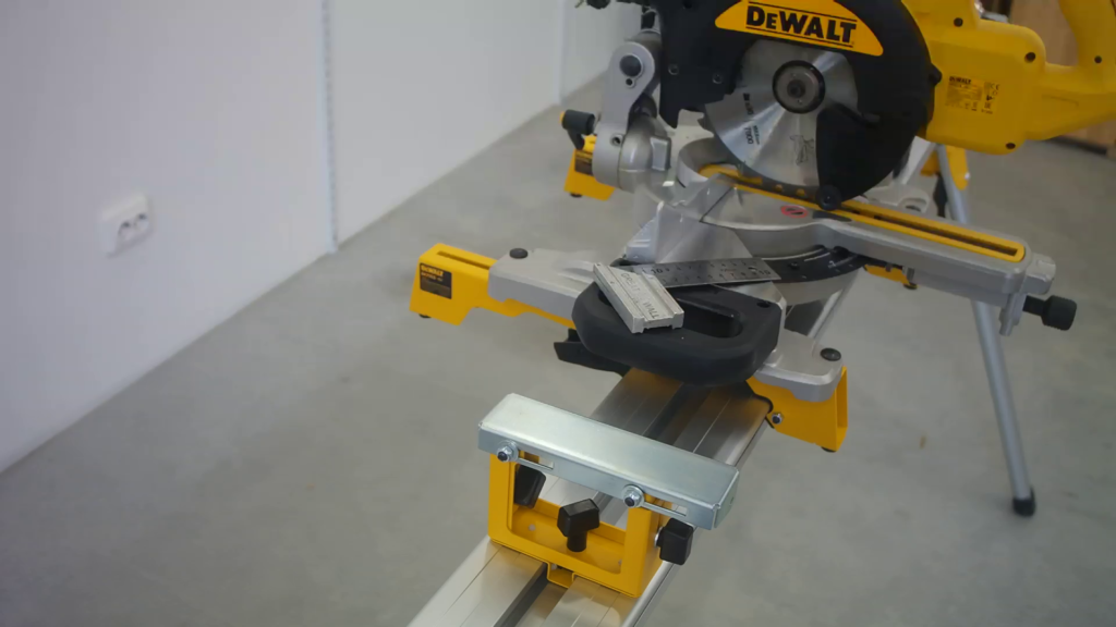
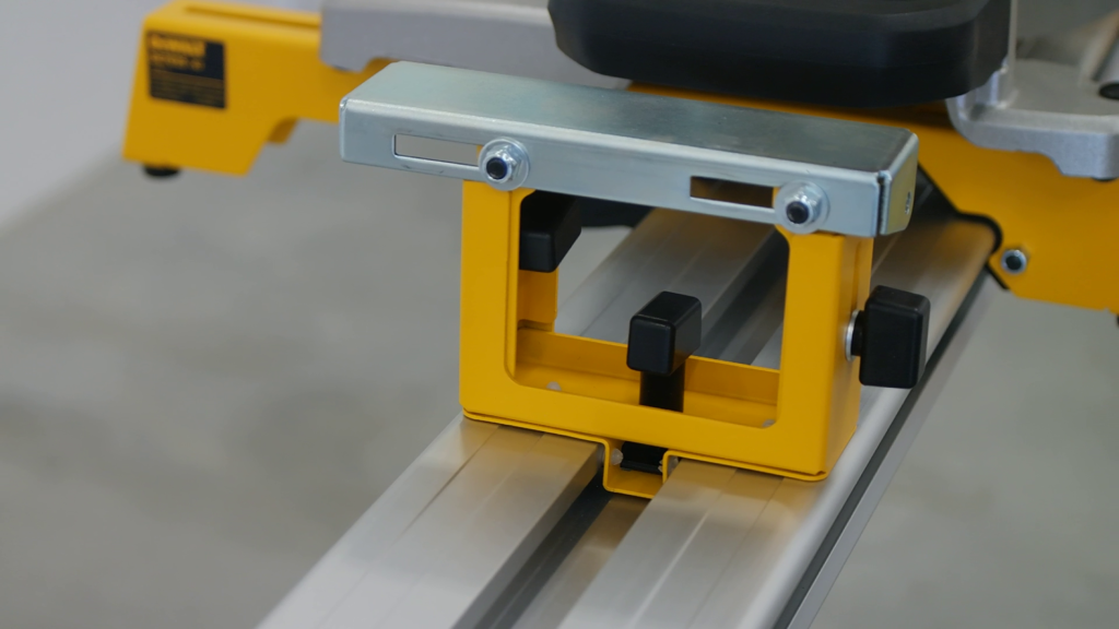
Loosen the nuts that lock the workpiece support in place and slide the support as far as possible toward the side where the height adjustment knob was moved (see Image #2). This gives you the best available surface for drilling the mounting hole for the Pedante T-head bolt.
Step 6: Mark the Drilling Position
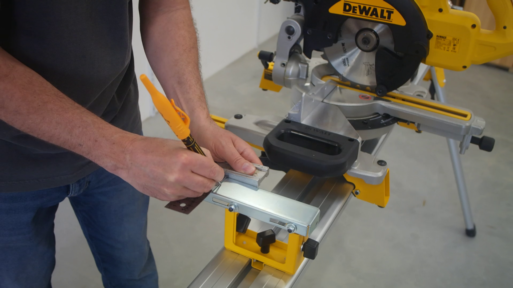
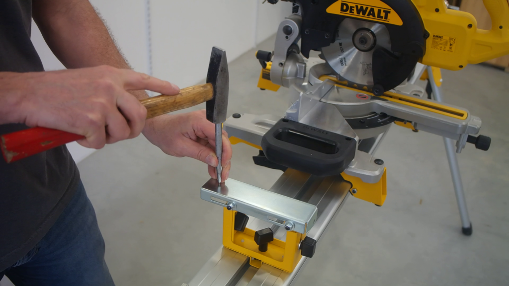
The hole you drill must line up with the groove on the bottom of the Pedante rail. Place the rail near the support and check where the groove will sit. Use a square to transfer the position accurately onto the support surface.
Mark the drilling position with a marker. After marking, use a center punch and hammer to make a small indent at the drilling point. This helps prevent the drill bit from slipping when you start drilling.
Take your time with this step. If the hole is too far out of position, it can make the final rail alignment difficult.
Step 7: Drill the Mounting Hole

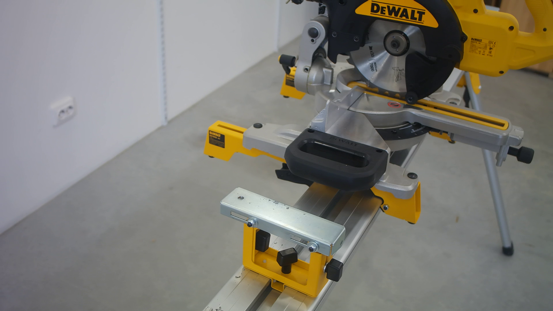
Drill the hole where you made the center punch mark.
The T-head bolts supplied with the Pedante LS-24-U are 8 mm in diameter, so the finished hole needs to be 8 mm. We recommend drilling a smaller pilot hole first. In this example, a 5 mm pilot hole was used before drilling the final 8 mm hole. Starting with a smaller drill bit reduces the chance of the larger bit slipping and helps keep the hole in the correct position.
Wear safety glasses while drilling. If needed, clamp the support so it cannot move. After drilling, remove any sharp burrs around the hole.
Step 8: Insert the T-Head Bolt
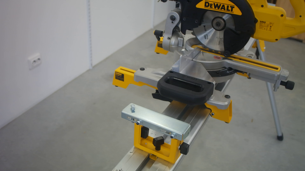
Insert one Pedante T-head bolt through the hole you just drilled.
The head of the bolt should be turned parallel to the length of the stand. This allows it to fit into the groove on the bottom of the Pedante rail later. Do not tighten anything yet. At this point, the bolt only needs to be in place and correctly oriented.
Step 9: Repeat the Process on the Second Support
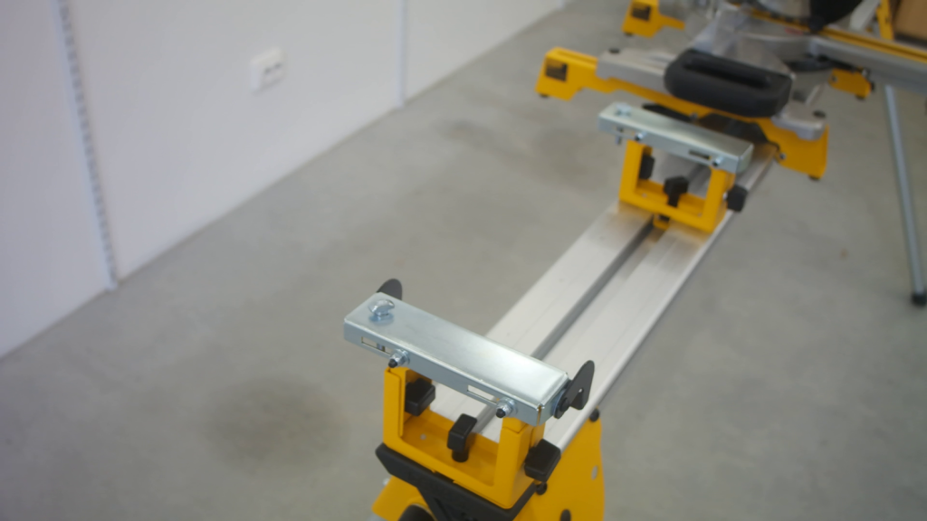
Repeat the same preparation steps on the second support on the Pedante side of the saw:
- Remove the original length stop, if needed.
- Move the height adjustment knob.
- Mark the drilling position.
- Center punch the mark.
- Drill the mounting hole.
- Insert the T-head bolt.
After this step, you should have two supports on the Pedante side of the saw. Each support should have one T-head bolt installed. These two bolts will hold the Pedante rail.
Step 10: Adjust the Support Heights
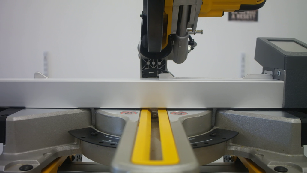
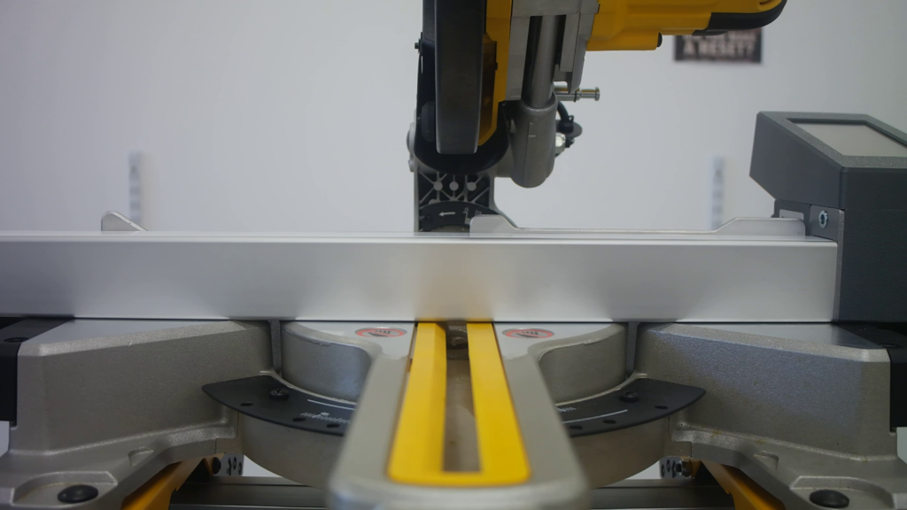
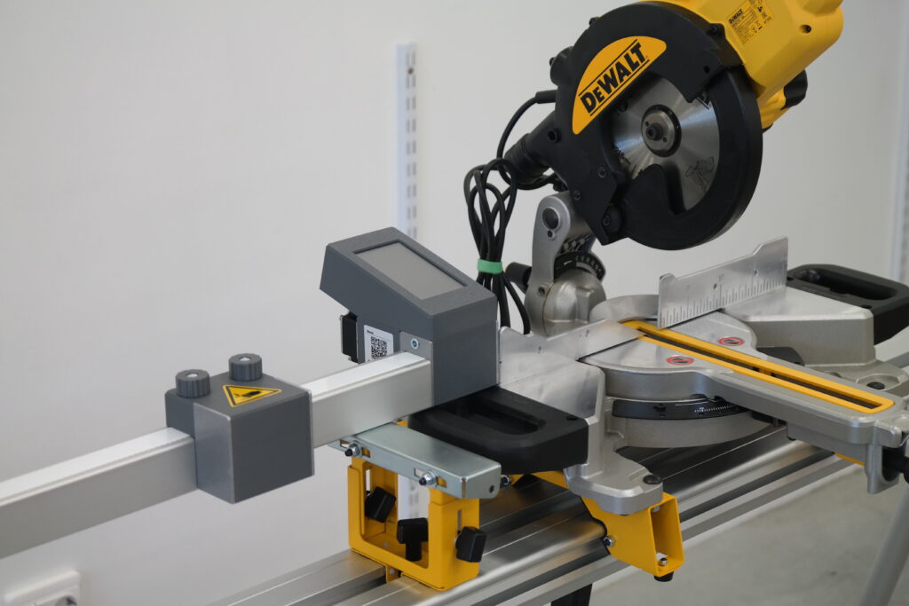
Place the Pedante digital miter saw fence on the miter saw turntable / saw table and use it as a reference to adjust the height of the DeWALT supports. The Pedante fence should be flush with the table area (see Image #2).
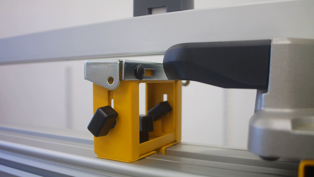
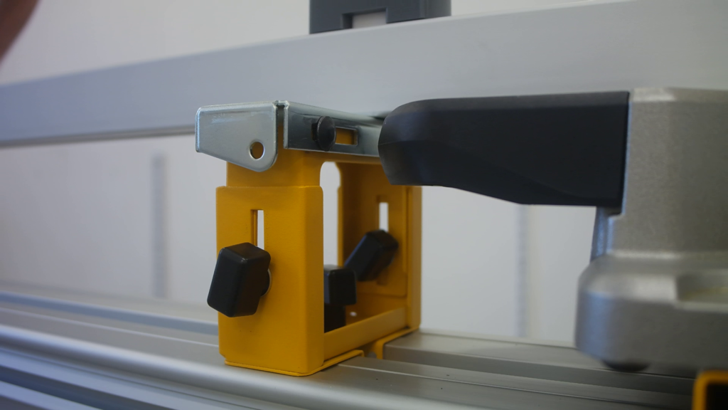
Loosen the height adjustment knobs and lift the supports until Pedante rail is level (see Image #4). When you have done that, tighten the knobs, so the support stays in place.
Step 11: Place Pedante on the Mounting Bolts
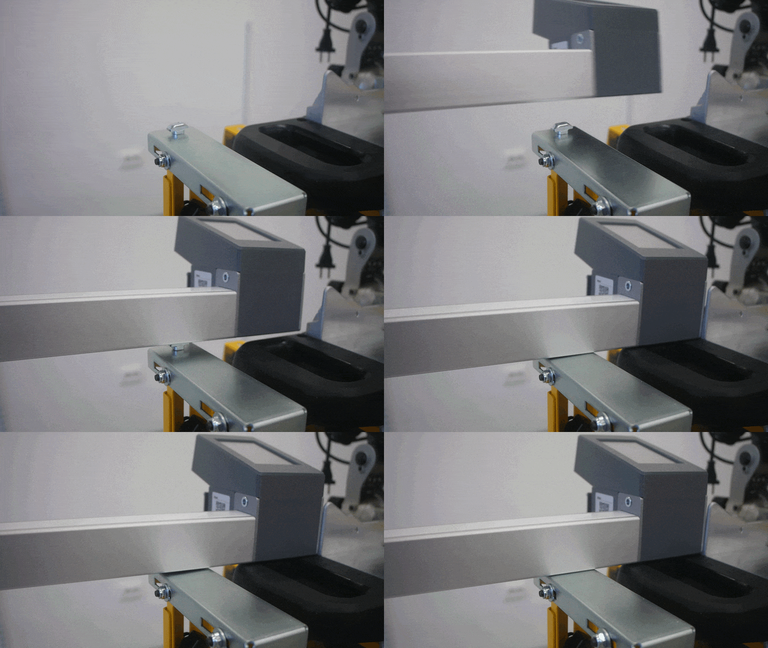
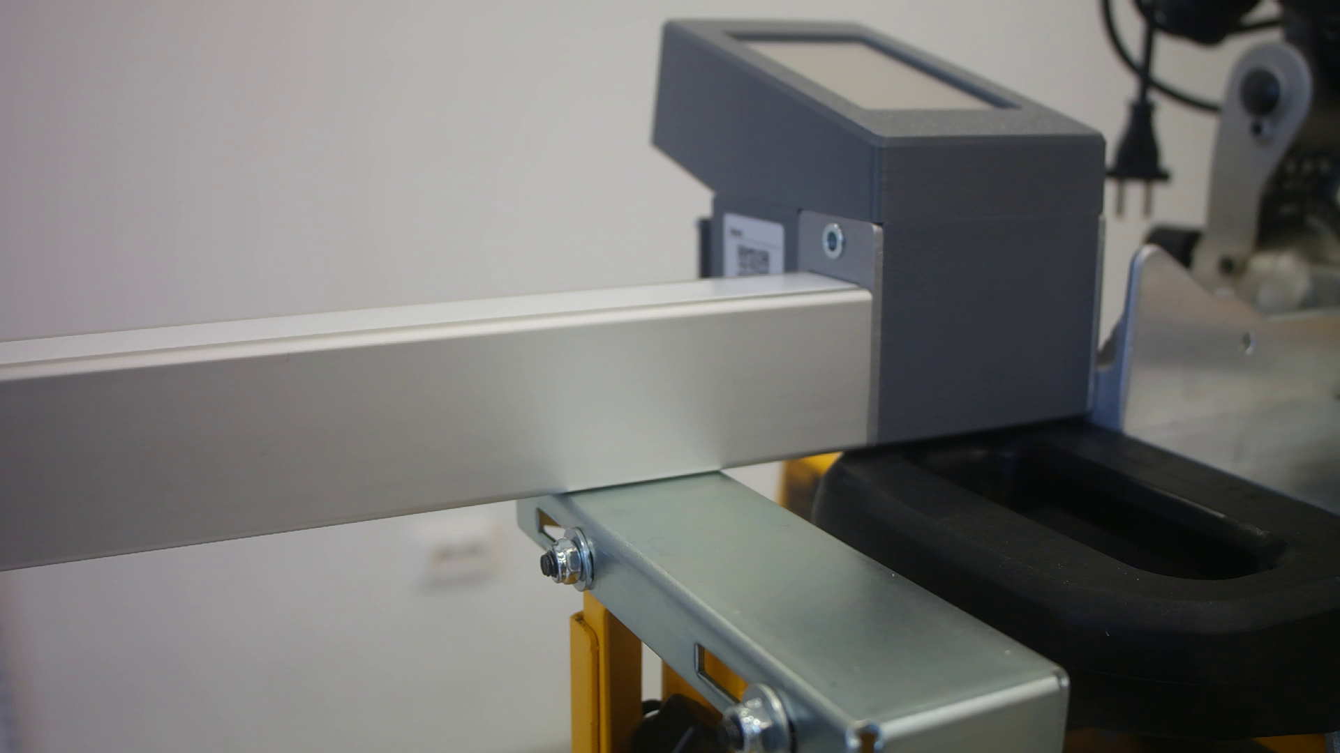
Lift the Pedante rail and move it into its mounting position on the side of the saw. Position it so the heads of the T-head bolts enter the groove on the bottom of the Pedante rail.
Move the control unit close to the saw, so the start of the rail sits correctly in relation to the saw fence area (see Image #2). The exact contact point may be different on other saws, so check your own setup carefully.
Make sure the rail does not interfere with:
- The saw blade
- The saw head movement
- The saw fence
- The turntable
- The support brackets
- The stop block travel
At this stage, the rail should be in the correct rough position, but final alignment still comes next.
Step 12: Lock the T-Head Bolts
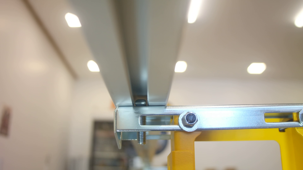
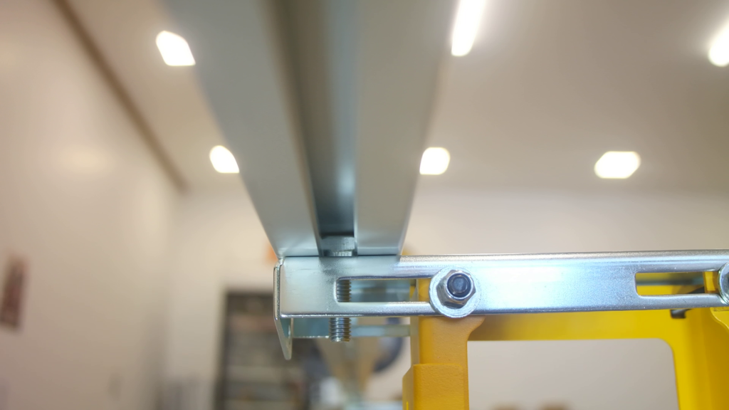
Turn the T-head bolts 90 degrees so they lock inside the groove on the bottom of the Pedante rail (see Image #2).
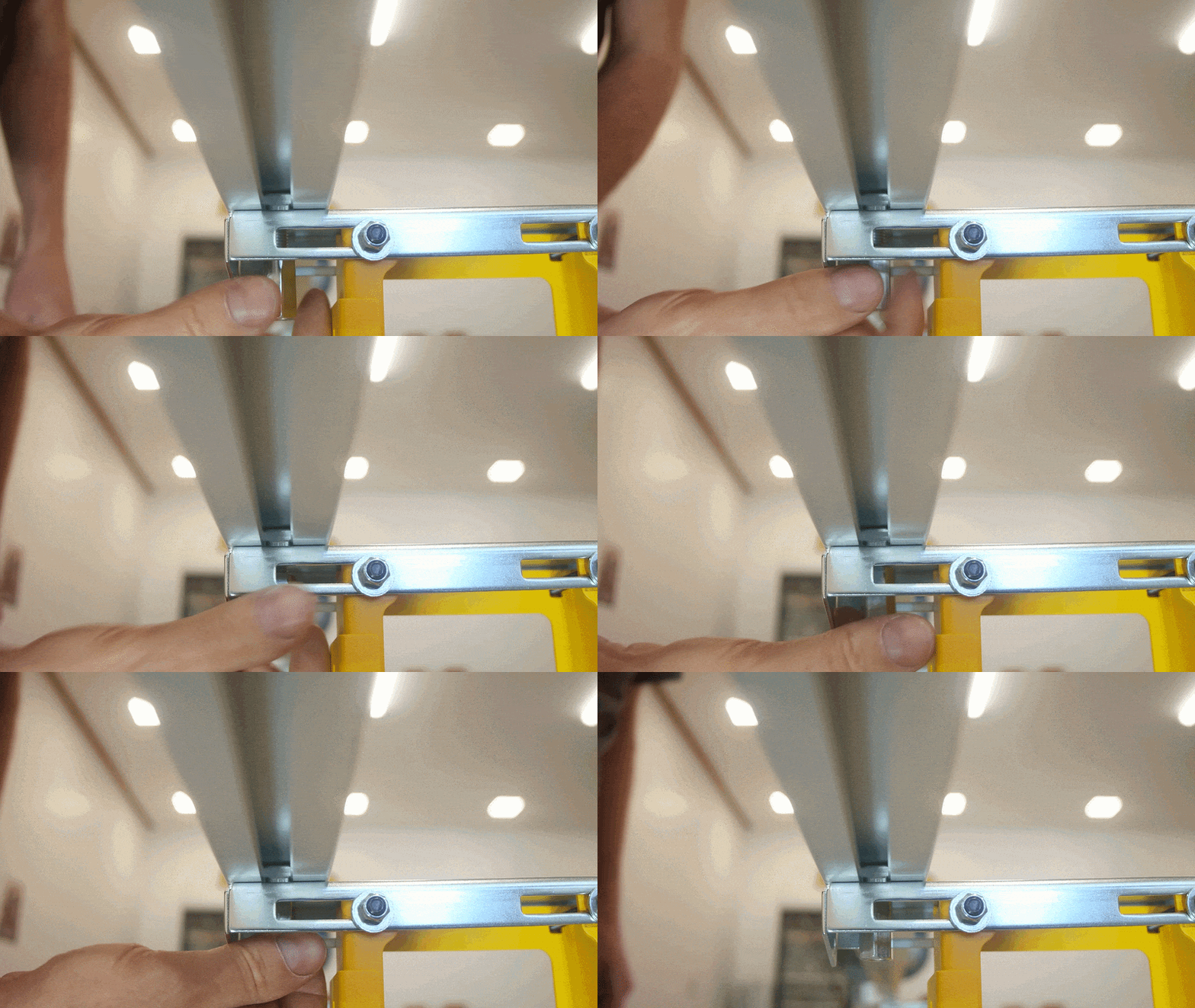
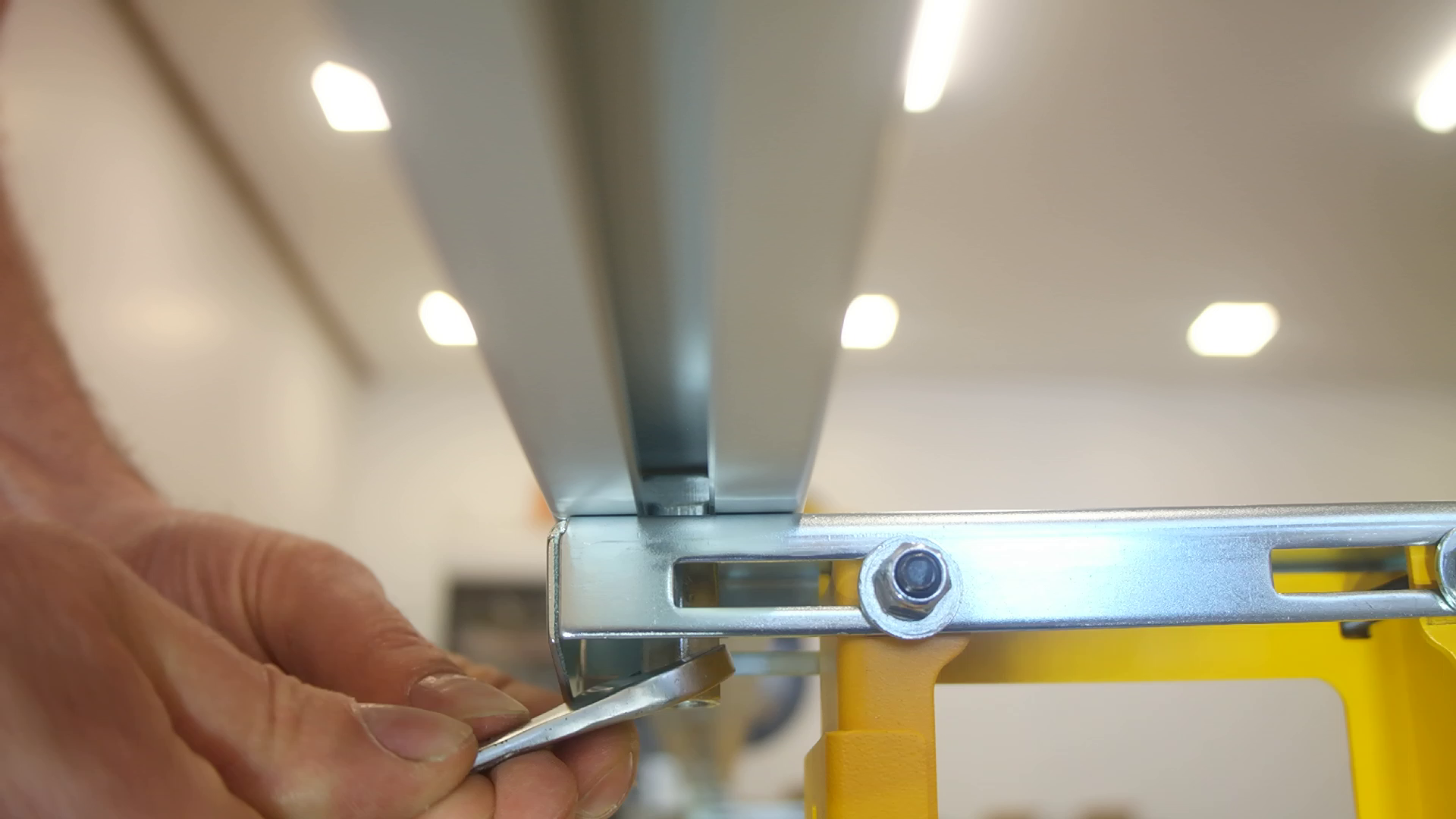
Then screw on the DIN6334 M8 extended nuts. Tighten the nuts with a wrench, but make sure the rail is aligned correctly before fully locking everything down.
Step 13: Align the Pedante Rail With the Saw Fence
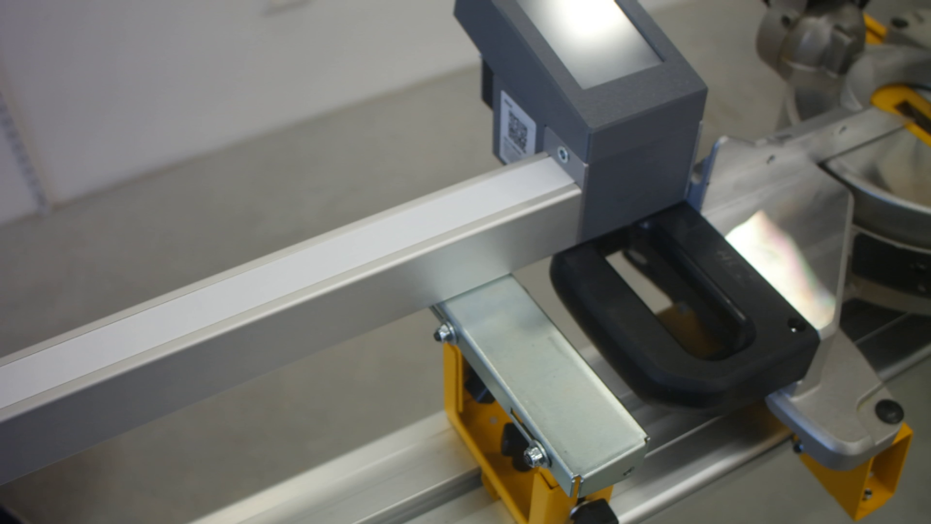
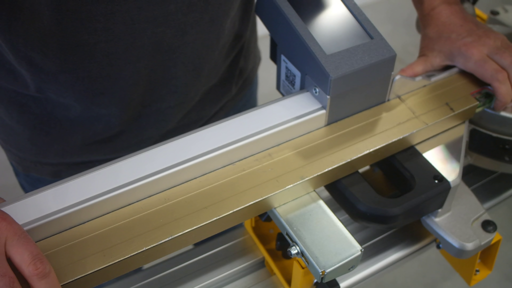
Loosen the nuts that lock the work support position.
Use a straight piece of wood or metal to align the Pedante rail with the saw fence. Place the straight edge against the saw fence and extend it along the Pedante rail. The Pedante rail should follow the same line as the saw fence.
You are checking that the rail does not point toward the blade or away from the blade. It should continue straight from the saw fence along the material path. When the rail is aligned, tighten the nuts that hold the work support in place.
After tightening, check the alignment again. Sometimes parts can move slightly while being tightened.
Step 14: Attach the Pedante Stop Block
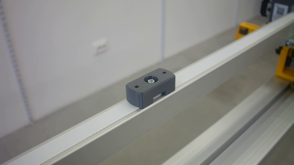
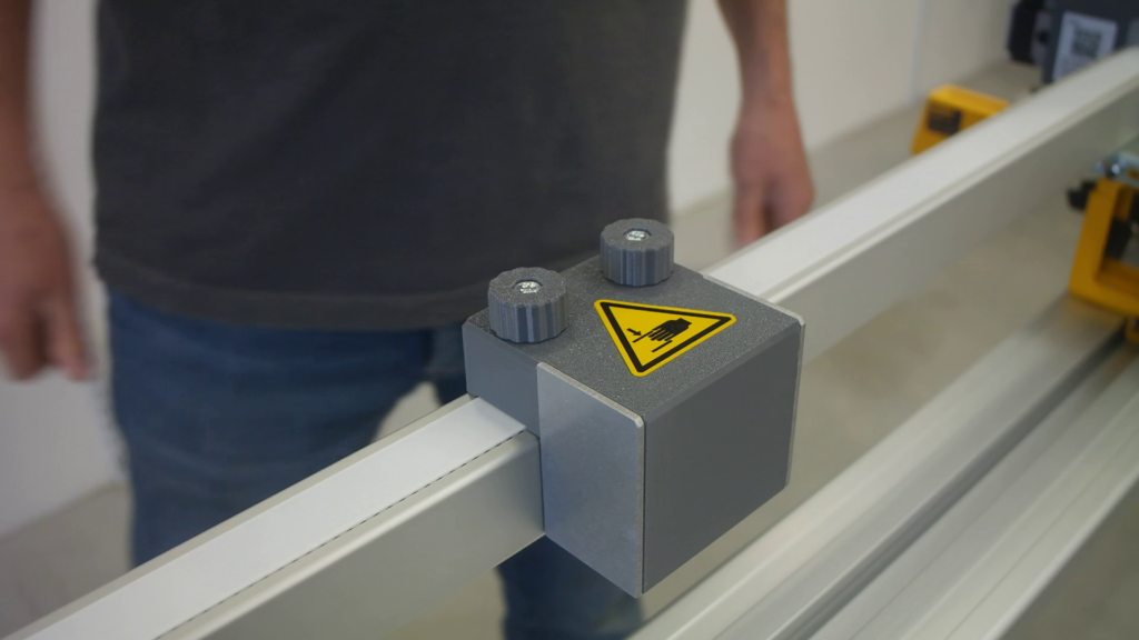
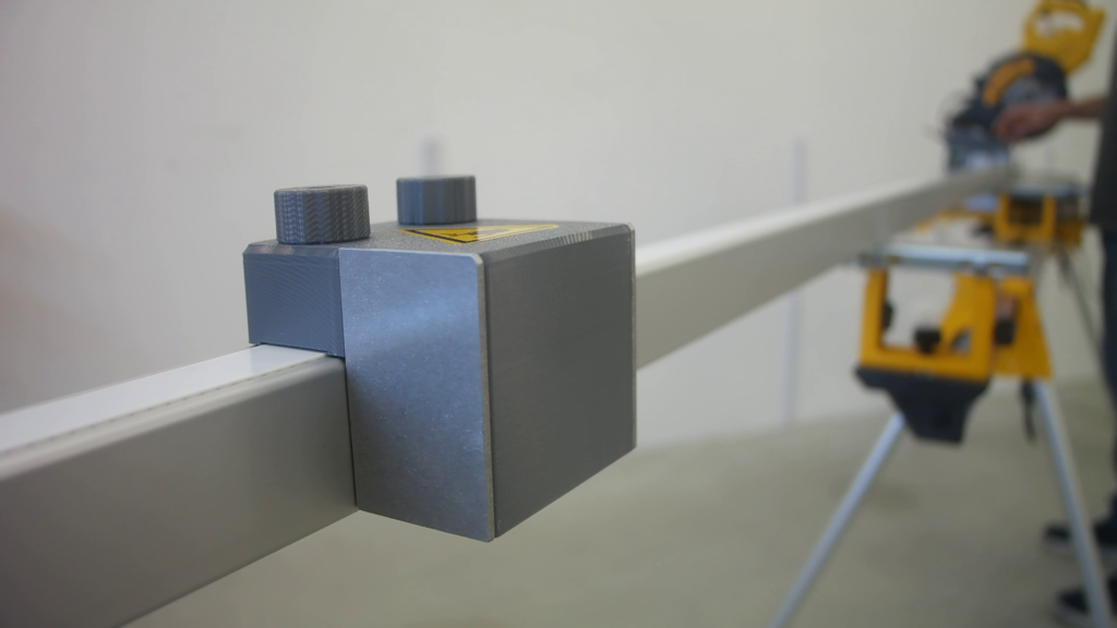
Attach the stop block to the Pedante rail. Place it on the rail and tighten the knobs. Then move it along the rail by hand to check that it travels freely. Make sure the stop block does not hit the supports, knobs, saw, or any other part of the setup.
Also check that the stop face is square to the material path. When a workpiece is pushed against the stop, the end of the material should touch the stop face cleanly.
Step 15: Final Check
Before powering on Pedante, check the complete installation. Go through the setup and confirm that:
- The saw is firmly mounted.
- The stand is stable.
- The work supports are locked.
- The height adjustment knobs are tight.
- The T-head bolts are locked in the Pedante rail.
- The extended nuts are tightened.
- The stop block moves freely.
- The workpiece can sit flat on the saw table and support area.
- Nothing interferes with the saw head, blade, or turntable.
Push a piece of scrap material gently against the stop block. The rail and supports should not slide, twist, or move. If anything moves, fix the mechanical issue before continuing.
Step 16: Connect and Power On Pedante
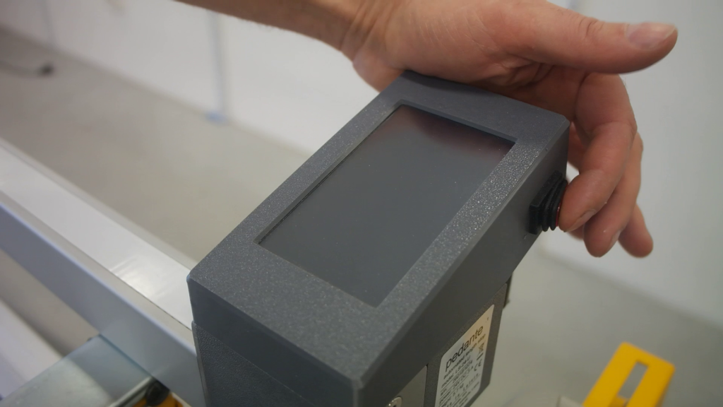
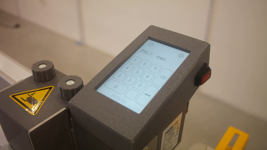
Plug in and turn on the Pedante control unit.
Pedante should be installed on the intended side of the saw before the first run. If the system has already been set up on the opposite side, it will need to be reset before setting it up again.
Do not start the first run until the physical installation is complete. The rail should already be straight, level, secure, and aligned with the saw fence. If the mechanical setup is wrong, calibration will not solve the problem.
Step 17: First Run and Calibration
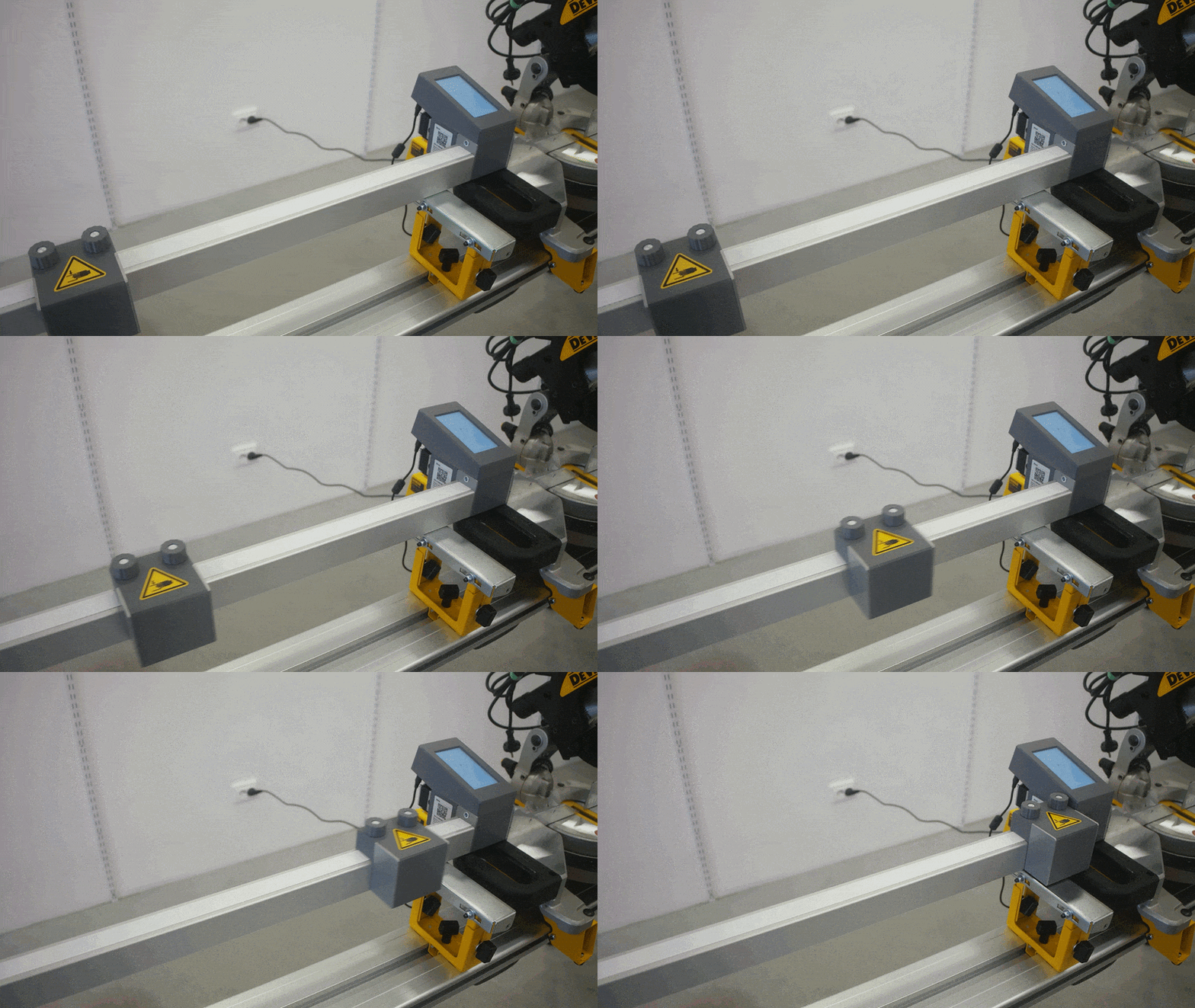
After installation, Pedante needs to run its self-setup program. During self-setup, the system detects its working range and which side of the saw it is mounted on.
After self-setup, the system must be calibrated. Calibration makes the length shown on the touchscreen match the real cut length.
Follow the official Pedante manual for the full calibration process. The basic idea is:
- Enter a test length on the touchscreen.
- Let the stop block move to position.
- Place a piece of scrap material against the saw fence and Pedante stop.
- Make a test cut.
- Measure the cut piece carefully.
- Compare the real cut length to the length shown on the screen.
- Press the calibration button.
- Enter the measured length of the cut piece.
If the cut length is consistent but slightly offset, calibration usually needs adjustment. If the cut length changes from one cut to the next, check the mechanical mounting first. Something may be loose, moving, or misaligned.
Step 17: The End